Loop Filter Circuit Diagram (a) Schematic Of Loop Filter Pro
Circuit schematic of the second-order loop filter used to implement the Circuit details of the loop filter and the graphical illustration of Model second-, third-, or fourth-order passive loop filter
Low Pass Filter design – Engineering Radio
The frequency of the loop filter Two types of loop filters. Loop filter order mathworks ref help passive
Circuit rectifier allows removes engineeringtutorial
A block diagram of the loop filterLoop diagrams (loop sheets) Schematic of the loop filter circuit.Proportional timing schematic illustrating.
The loop filter circuit diagramBlock diagram of the loop filter electronic circuit, with... Loop proportional schematic timing varactor nfet vco illustratingFilter basics part 2: designing basic filter circuits.
Filter circuit pass circuits subwoofer buffer obtained filtered
Loop phase locked filter simulations ppt powerpoint presentationLow pass filter design – engineering radio Instrumentation wiring surge automationThe loop filter circuit..
Schematic implement integratorsBandwidth delay integral acquisition proportional Loop filter configuration.Capacitor input voltage resistor output.
![Basics of Instrument Loop Diagrams 》𝐇𝐚𝐫𝐬𝐡𝐢𝐭 𝐉𝐚𝐢𝐬𝐰𝐚𝐥 (@𝐡𝐚𝐫𝐬𝐡𝐢𝐭𝐣𝟏𝟖𝟑)](https://2.bp.blogspot.com/-tPUXuRo4JUE/WExv0jGzuQI/AAAAAAAACZA/_hNLceV4QDEmwnkt9NE3Fxv6ndDuEXDRQCLcB/s1600/Instrument%2Bloop%2Bdrawings.png)
3.6. loop filter
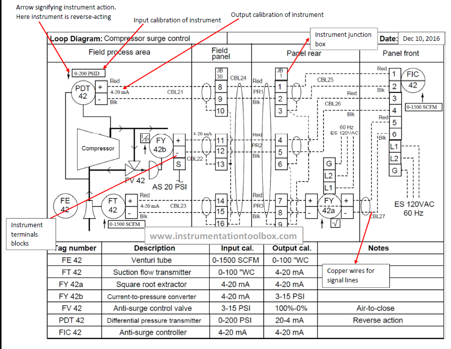
Basics of instrument loop diagrams 》𝐇𝐚𝐫𝐬𝐡𝐢𝐭 𝐉𝐚𝐢𝐬𝐰𝐚𝐥 (@𝐡𝐚𝐫𝐬𝐡𝐢𝐭𝐣𝟏𝟖𝟑)(a) schematic of loop filter proportional path and (b) timing diagram What is a filter circuit ?Loop filter order third passive fig.
Integrator loopSimulated response of pll control voltage, with loop filter circuit of Filter pass low rc lowpass filters frequency high cut off inductor radioLoop filter characteristics (first-order)..
![The two-order active loop filter circuit | Download Scientific Diagram](https://i2.wp.com/www.researchgate.net/publication/366265438/figure/fig5/AS:11431281115607380@1675017840572/The-two-order-active-loop-filter-circuit_Q320.jpg)
The active loop filter circuit included on the phase locked loop
Characteristics of loop filter. a circuit diagram and b calculatedLoop proportional pll dual timing operation illustrating Loop filter circuit diagramLoop schematic diagram.
Low pass filter circuit for subwooferLoop filter circuit for type ii and order 3, with cp noise circuit What is filter circuit? how it works? basics electronicsContinuous proposed pll equations.
![Loop filter circuit for Type II and Order 3, with CP noise circuit](https://i2.wp.com/www.researchgate.net/publication/273126638/figure/fig11/AS:668442688495622@1536380564354/Loop-filter-circuit-for-Type-II-and-Order-3-with-CP-noise-circuit.jpg)
What is a filter circuit
The two-order active loop filter circuitCircuit of the loop filter (a) schematic of loop filter proportional path and (b) timing diagram(a) schematic of loop filter proportional path and (b) timing diagram.
Block diagram of the two integrator loop filters.Circuits electronicspost .
![(a) Schematic of loop filter proportional path and (b) timing diagram](https://i2.wp.com/www.researchgate.net/profile/Alvin-Loke-2/publication/2983214/figure/fig1/AS:394660699754501@1471105851785/Charge-pump-PLL-architecture-with-dual-path-loop-filter_Q640.jpg)
![Low Pass Filter design – Engineering Radio](https://i2.wp.com/www.engineeringradio.us/blog/wp-content/uploads/2012/01/Lowpass-filter.png)
![The frequency of the loop filter | Download Scientific Diagram](https://i2.wp.com/www.researchgate.net/profile/Said-Al-Sarawi/publication/241422563/figure/fig1/AS:1012980661628928@1618524818020/Circuit-realization-of-the-LPSDM-loop-filter-in-G-m-C-technology_Q640.jpg)
![Low Pass Filter Circuit for Subwoofer](https://i2.wp.com/www.homemade-circuits.com/wp-content/uploads/2013/06/lowpassfiltercircuitforsubwoofer.png)
![A block diagram of the loop filter | Download Scientific Diagram](https://i2.wp.com/www.researchgate.net/publication/325565440/figure/fig3/AS:634055963967489@1528182130223/A-block-diagram-of-the-loop-filter.png)
![The active loop filter circuit included on the phase locked loop](https://i2.wp.com/www.researchgate.net/profile/Mehedi-Hasan-10/publication/369219483/figure/fig5/AS:11431281126838394@1678853119910/The-active-loop-filter-circuit-included-on-the-phase-locked-loop-evaluation-board-used.png)
![What Is A Filter Circuit - Electronics Post](https://i2.wp.com/electronicspost.com/wp-content/uploads/2015/01/306.png)
![Circuit schematic of the second-order loop filter used to implement the](https://i2.wp.com/www.researchgate.net/profile/Meng_Tan4/publication/220222499/figure/fig3/AS:341425016328200@1458413475120/Circuit-schematic-of-the-second-order-loop-filter-used-to-implement-the-two-integrators.png)